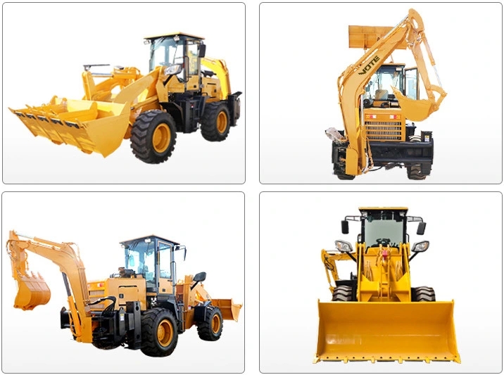

The working principle of a loader involves two main parts: power transmission and the operation of the working device.

The power transmission system is the core of the loader. The power system of a loader generally uses a diesel engine system, which is like the "heart" of the loader. It converts the thermal energy generated by the combustion of fuel in the cylinder into mechanical energy, providing a continuous power supply for the loader. The diesel engine completes a working cycle after four continuous strokes: intake, compression, power, and exhaust, continuously outputting power to the outside.
After the power is output from the diesel engine, it passes through the torque converter. The torque converter is like a magical "power regulator". It is used to improve the power performance of the loader when the operating torque changes greatly, giving it automatic adaptability and the ability to achieve stepless speed regulation. The torque converter has a single - stage, two - phase, four - element dual - turbine structure, consisting of a pump impeller, a primary turbine, a secondary turbine, and a guide wheel. The pump impeller is connected to the engine flywheel through an elastic plate. When the pump impeller rotates, it drives the oil in the circular flow, giving it a certain amount of kinetic energy. The oil then pushes the primary and secondary turbines, and drives the transmission through the primary turbine output gear and the secondary turbine output gear connected to them.
The gearbox is the main transmission component of the loader. Its function is similar to that of an automobile gearbox, changing the transmission ratio, meeting the needs of the loader for forward and backward movement, and enabling it to stop while the engine is running. The gearbox is divided into two parts: the speed - change transmission mechanism and the speed - change control mechanism. The transmission mechanism includes the input shaft (active shaft), output shaft (driven shaft), intermediate transmission shaft, reverse shaft, and various transmission gears, etc. The power of the active shaft is transmitted to the driven shaft under load through the meshing of different gear pairs. The control mechanism is used to operate the speed - change gears of the gearbox, making them engage or disengage, brake or separate, so that the loader can obtain different traveling speeds and traction forces and change the traveling direction when necessary.
After passing through the gearbox, the power is transmitted to the front and rear axles through the drive shaft, thereby driving the wheels to move. The drive axle is located at the end of the transmission system. It transmits the engine torque from the universal joint and the gearbox to the drive wheels. After reducing the speed and increasing the torque and changing the direction of power transmission, it enables the loader to move and allows the left and right drive wheels to rotate at different speeds, thus achieving steering. When the loader needs to brake, after stepping on the brake pedal, the compressed air in the air storage tank enters the front and rear drive axles through the brake valve respectively. It pushes the pistons of the respective booster cylinders and the master brake cylinder, creating high - pressure brake fluid in the master cylinder. The high - pressure brake fluid then enters the brakes of the front and rear drive axles along the pipelines, pushing the brake caliper pistons and friction pads against the brake discs, thus achieving braking.
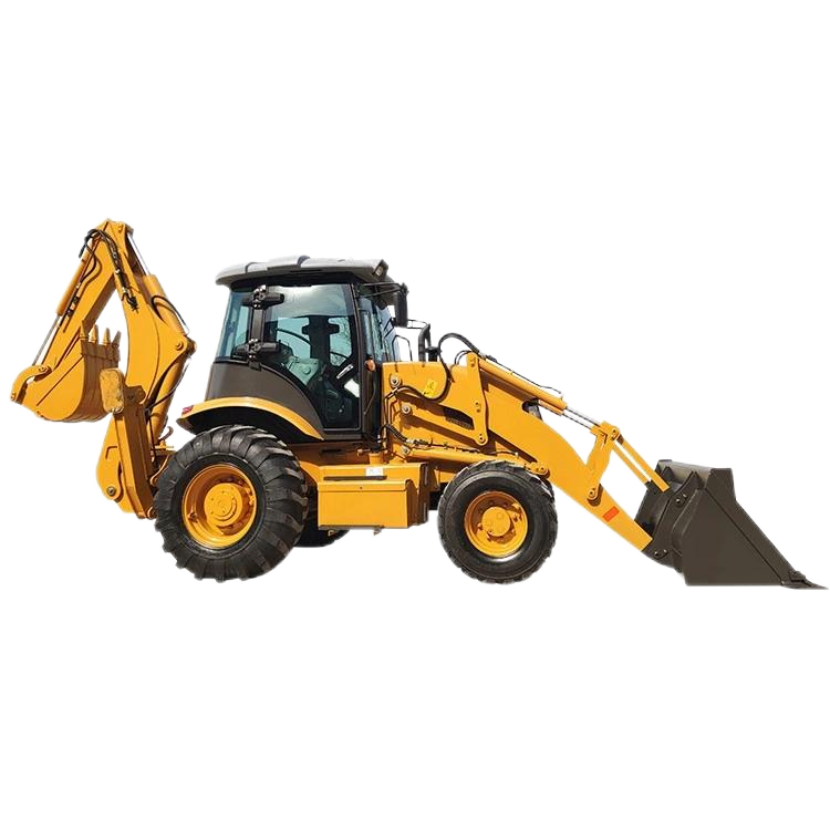
The working device of the loader is also crucial for it to complete various operations. The entire working device is hinged to the frame and generally consists of a bucket, boom, rocker arm, connecting rod, and its hydraulic control system. The bucket is hinged to the bucket - tilting cylinder through the connecting rod and rocker arm, and the boom is hinged to the frame and the boom cylinder. The tilting of the bucket and the lifting of the boom are hydraulically controlled. When the bucket cylinder is locked and the boom cylinder lifts or lowers, the linkage mechanism makes the bucket move up and down or move almost horizontally to prevent the bucket from tilting and spilling the materials. When the boom is in any position and the bucket rotates around the hinge point with the boom for unloading, the bucket discharges the materials. After unloading, when the boom descends, the bucket automatically levels.
There are usually two operation methods for a loader to load materials: the single - insertion loading method and the simultaneous - insertion - and - lifting loading method (also known as the compound loading method). When using the single - insertion loading method, the loader inserts the bucket into the material pile with full driving force, then uses the hydraulic system to tilt the bucket upward, and finally makes the loader reverse to unload the materials into a truck. When using the compound loading method, the loading operation is completed by using multiple compound actions of inserting and lifting the bucket simultaneously.